RootMaster

Note
This describes the revision 3 of the hardware. For the description of revision 2: RootMaster r2
Warning
The Raspberry Pi has been rotated 180° from revision 2. Please note the revision of your board before connecting the Raspberry Pi since it will be damaged if connected the wrong way!
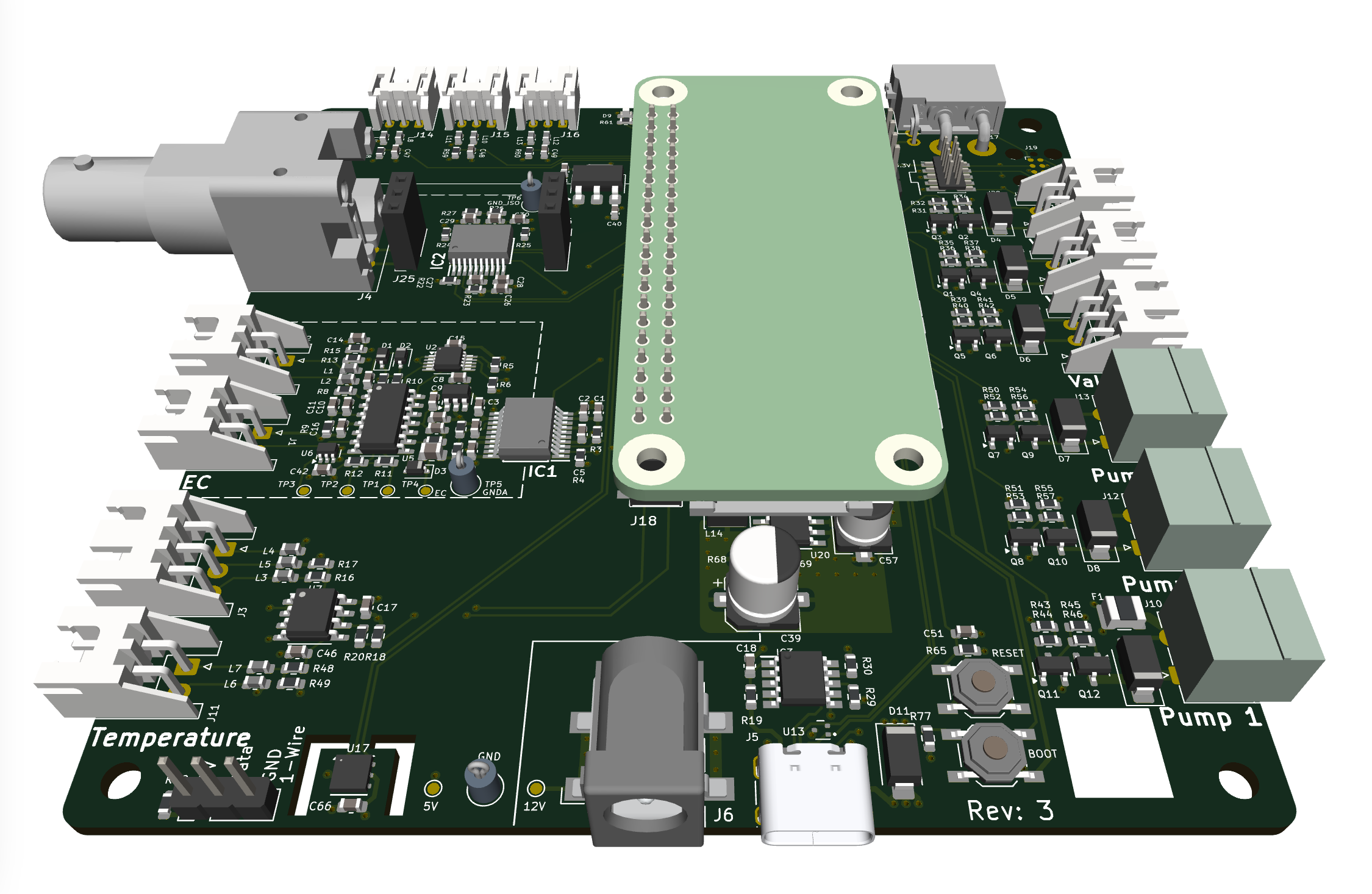
Changes from revision 2
The major changes from revision 2 are:
pH block changed to support external sensor hat. Either our own or EZO pH from Atlas Scientific
Support for either BNC or SMA for pH probe
Raspberry Pi rotated 180°
Fixed known issues from Rev 2
Power
The RootMaster can be powered in two ways: via USB Power Delivery (USB-PD) or through a 12V barrel jack. The USB-PD input allows for flexible power options and can be used with a variety of USB-C power adapters. Please note that the USB-C power adapter must be 12 V capable. The 12 V barrel jack provides a more traditional power input method, suitable for use with standard 12 V power supplies.
STM32G473
At the core there is a STM32G473 that is connected to all external peripherals.
Hardware rev
The hardware revision can be read through 3 gpios. On rev 3 rev 0 should be read as 1 and rev 1 and rev 2 as 0.
Pin Number | Pin Name | Connected To | Note |
|---|---|---|---|
8 | PA0 | HW rev 0 | Should be read as 1 |
9 | PA1 | HW rev 1 | Should be read as 0 |
10 | PA2 | HW rev 2 | Should be read as 0 |
CAN-FD
There is a CANbus connecting the STM32 to Raspberry Pi and the external connection. This is CAN-FD compatible with a maximum speed of 1 Mbit/s. It is connected to the FDCAN3 peripheral in the MCU.
Pin Number | Pin Name | Connected To | Note |
|---|---|---|---|
40 | PB3 | CAN-TX | |
41 | PB4 | CAN-RX |
LEDs
RootMaster has two leds for status and debug. Both yellow.
Pin Number | Pin Name | Connected To | Note |
|---|---|---|---|
2 | PC13 | LED1 | Active Low |
3 | PC14 | LED2 | Active Low |
Internal temperature and humidity sensor
There is an internal temperature and humidity sensor HDC1080 connected to I2C0.
Note: The i2c bus is also shared with the EC/temp sensor.
Pin Number | Pin Name | Connected To | Note |
|---|---|---|---|
39 | PA15 | I2C0 SCL | |
44 | PB7 | I2C0 SDA |
Temperature
The NTC temperature sensor is connected to the STM32G473 on pin 12 (PA4). This sensor is used to measure the temperature of the nutrient solution. The resistance of the NTC decreases as the temperature increases, and this change in resistance is measured by the ADC to determine the temperature.
The NTC temperature sensor is connected as part of a voltage divider circuit. The voltage divider is formed by the NTC thermistor and a fixed 49.9kΩ resistor. The output voltage of the divider, which varies with temperature, is fed into the ADC of the STM32G473 to measure the temperature.
Since the ADC of the STM32G473 cannot measure signals higher than 3.3V the signal is fed to a second stage dampening made up by another voltage divider consisting of a 18kΩ and a 33kΩ resistor. This scales the signal from 0-5V to 0-3.235V.

The resistance for the NTC thermistor can be calculated using the following formula given the ADC is 12 bit:
If we replace the constants then the formula can be simplified to:
Pin Number | Pin Name | Connected To | Note |
|---|---|---|---|
12 | PA4 | NTC Temperature | Analog input |
pH
The pH sensor interface must be used together with one of the sensor hats. This interface is connected to the i2c bus I2C1. Please see the respective documentation for each on how to integrate them into the software.
There is a GPIO on RootMaster that enables the pH peripheral that must be enabled before any readings can be performed.
Pin Number | Pin Name | Connected To | Note |
|---|---|---|---|
14 | PA6 | pH disable | Active high, must be low to turn on sensor readings |
30 | PA8 | I2C1 SDA | |
31 | PA9 | I2C1 SCL |
EC and temperature
Pin Number | Pin Name | Connected To | Note |
|---|---|---|---|
13 | PA5 | EC disable | Active high, must be low to turn on sensor readings |
39 | PA15 | I2C0 SCL | Shared with temp/hum |
44 | PB7 | I2C0 SDA | Shared with temp/hum |
EC
The EC interface is using an ADS1115 ADC connected to I2C0. The 7 bit i2c address is 0x48. The EC value will be converted to a voltage on the AIN0 pin on the ADC. To work with as many probes as possible it is possible to set the gain using a MCP4017 digital potentiometer at the 7 bit address 0x2F. There is also a GPIO that enables the EC peripheral that must be enabled before any readings can be performed.
Temperature
There is a NTC interface connected to the same ADC as the EC on the AIN2 pin. The temperature NTC is connected as the bottom part of a voltage divider connected between 5 V and GND. The upper resistor is 49.9kΩ and must be taken into account when calculating the temperature.

Flow
The flow meter is connected to a GPIO pin and sends pulses proportional to the flow rate. Each pulse represents a fixed volume of liquid passing through the meter. The STM32G473 counts these pulses to measure the flow rate and total volume.
Pin Number | Pin Name | Connected To | Note |
|---|---|---|---|
11 | PA3 | Flow meter | Pulse input |
Digital in
There are 3 digital inputs that can be connected to various NC/NO sensors such as water level sensor or similar. All three inputs have pull ups connected to 3.3 V.
Pin Number | Pin Name | Connected To | Note |
|---|---|---|---|
46 | PB9 | IN 1 | |
43 | PB6 | IN 2 | |
42 | PB5 | IN 3 |
12V high side switches
There are 6 high side switch outputs that can be used to connect valves or pumps. These outputs are capable of switching 0-12 V and are controlled using PWM signals from the STM32G473. Each switch can be individually controlled to regulate the power supplied to the connected devices.
Pin Number | Pin Name | Connected To | Note |
|---|---|---|---|
29 | PB15 | Valve 1 | |
28 | PB14 | Valve 2 | |
27 | PB13 | Valve 3 | |
15 | PA7 | Pump 1 | TIM3 CH2 |
17 | PB1 | Pump 2 | TIM3 CH4 |
25 | PB11 | Pump 3 | TIM2 CH4 |
Raspberry Pi
The Raspberry Pi is used as the main controller for the RootMaster. To enable CAN on the Raspberry Pi, you need to modify the device tree overlay settings.
Enabling CAN
To enable the CANbus on the Raspberry Pi, follow these steps:
Add the file
rootmaster.dtboto/boot/firmware/overlayOpen the systemd network configuration file:
sudo nano /etc/systemd/network/80-can.network
Add the following:
[Match]
Name=can*

[CAN]
BitRate=1000000
DataBitRate=1000000
FDMode=yes
Save the file and exit the editor.
Enable systemd-networkd to bring up the CAN interface
sudo systemctl enable systemd-networkd
Reboot the Raspberry Pi to apply the changes:
sudo reboot
1-Wire
To 1-Wire interface will be activated automatically by the rootmaster.dtb overlay
Verify that the 1-Wire devices are detected:
ls /sys/bus/w1/devices/
You should see a directory for each connected 1-Wire device.
Compatible peripherals
This is a list of peripherals that has been tested.
Peripheral | Link |
|---|---|
Water pump 12V | |
EC + temperature | |
pH probe | |
pH probe |